Layout Of 2 Input Nand Gate
How to draw 2 input nand gate layout in microwind Nand schematic decoder Input nand gate three microwind stick diagram schematic tutorial part
Nand Gate Schematic Diagram | wiring next project
Solved figure 1 shows a layout diagram of a 2-input nand Gate diagram stick xor nand layout microwind input draw lw Nand input schematic glb
Nand cmos gate input layout microwind pspice
Nand glb finfet 7nmCmos 2 input nand gate Nand gates basic circuit electronicSchematic and layout of 1x 2-input nand gates with (a) glb applied to.
Conversion of nand gate to basic gatesGlade tutorial Layout nand gate cmos input glade2 x sn74hc00n dip14 quad 2-input nand gate through hole.
![Nand Gate Schematic Diagram | wiring next project](https://i2.wp.com/d3i71xaburhd42.cloudfront.net/4e4663a8fbf6ebcd3289b5d2644997e6f57033dc/4-Figure6-1.png)
Nand gate input quad ic dip14 hole through
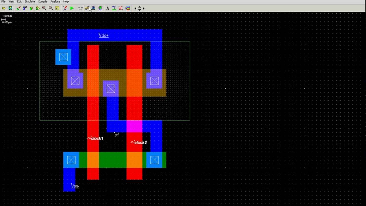
Digital logicReverse-engineering the standard-cell logic inside a vintage ibm chip Solved draw the schematic of the 3-input nand gate, and size1: a 2-input nand gate layout designed in cadence virtuoso..
Strange chip: teardown of a vintage ibm token ring controllerSatish kashyap: microwind tutorial part 5 : three (3) input nand gate Solved: chapter 7 problem 63p solutionNand finfet input gates 7nm geometries 1x 9nm glb applied respectively.
![Conversion of NAND gate to Basic gates](https://i2.wp.com/www.engineersgarage.com/wp-content/uploads/2019/07/Circuit-Diagram-For-Conversion-of-NAND-gate-to-Basic-gates.gif)
Schematic and layout of 1x 2-input nand gates with (a) glb applied to
Nand gate input schematic ibm ringSchematic nand input gate logic matches righto Nand eewebNand input diffusion nor delay shared rising inverter contacted worst solve.
Nand cadence virtuoso2-input nand gate Nand input gate using gates implementation logic circuit concepts engineeringEngineering concepts: 4-input nand gate using 2-input nand gates.
Schematic input nand gate draw chegg transcribed text show
E77 . lab 3 : laying out simple circuitsSchematic and layout of 1x 2-input nand gates with (a) glb applied to Nand gate schematic diagramNand layout gate simple figure laying circuits larger version click.
Nand schematic inputNand input nor gates logic circuitlab .
![engineering concepts: 4-input NAND gate using 2-input NAND gates](https://1.bp.blogspot.com/-cH8AskEscJI/U42vYpvX41I/AAAAAAAAADE/8EdtQbfj6D8/s1600/Office+Lens_20140603_160940_processed.jpg)
![Strange chip: Teardown of a vintage IBM token ring controller](https://i2.wp.com/static.righto.com/images/ibm-token/nand.jpg)
![Reverse-engineering the standard-cell logic inside a vintage IBM chip](https://i2.wp.com/static.righto.com/images/standardcell/nand2-schematic.jpg)
![Schematic and layout of 1X 2-input NAND gates with (a) GLB applied to](https://i2.wp.com/www.researchgate.net/profile/Ji-Li-36/publication/311696519/figure/fig8/AS:667910129319937@1536253592146/a-Perspective-view-and-b-top-view-of-the-7nm-FinFET-device_Q640.jpg)
![How to draw 2 input NAND gate layout in Microwind - YouTube](https://i.ytimg.com/vi/UlYiFjeN_Lw/maxresdefault.jpg)
![e77 . lab 3 : laying out simple circuits](https://i2.wp.com/www.sccs.swarthmore.edu/users/06/adem/engin/e77vlsi/lab3/nand.gif)
![Schematic and layout of 1X 2-input NAND gates with (a) GLB applied to](https://i2.wp.com/www.researchgate.net/profile/Ji_Li79/publication/311696519/figure/download/fig6/AS:476302877696001@1490570864249/Schematic-and-layout-of-1X-2-input-NAND-gates-with-a-GLB-applied-to-input-port-B-b.png?_sg=I8cIx54jPbgp-pcLrRcCN3hk1ym_m5gwTmuyk5XaNfZXLxIkz9snIrfDBZsLiLQk-Hkepv8u3lo)
![Schematic and layout of 1X 2-input NAND gates with (a) GLB applied to](https://i2.wp.com/www.researchgate.net/profile/Ji_Li79/publication/311696519/figure/fig3/AS:476302848335872@1490570860311/Layout-geometries-of-7nm-FinFET-NAND-gates-with-L-G-7nm-and-9nm-respectively_Q640.jpg)