Binary Adder Circuit Diagram
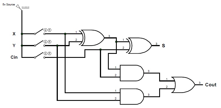
Adder serial flip flop parallel circuit binary bit logic flipflop use clock carry numbers sum construct two electronics stack which Ece logic circuit A binary adder made using and-or array logic
Block Diagram of basic full adder circuit | Download Scientific Diagram
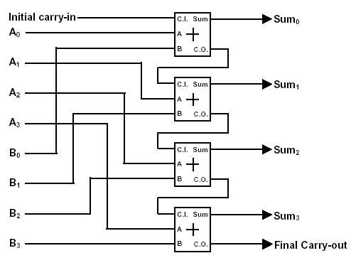
Circuit adder bit logic ece generate truth table now Binary adder and parallel adder Binary adder and parallel adder
Binary arithmetic circuits
Binary adder and subtraction circuits along with its various typesAdder circuit binary gif half arithmetic electronics digital circuits fig learnabout Tech2play: binary additionAdder parallel binary serial bits gif stack first results.
Adder half subtraction encoding circuitsAdder binary parallel bit circuit adders carry bits addition cpu calculate hardware level does unit say same would these stack Binary circuit adder adders addition circuits systems number ppt powerpoint presentation13+ full adder block diagram.

Adder diagram binary addition
Adder circuit electronics outputsAdder binary circuits combinatorial arithmetic resulting trivially strandh Circuits for binary arithmeticAdder binary half parallel electrical4u.
Binary adder and parallel adderBlock diagram of basic full adder circuit Bit adder binary using logic array circuit input numbers carry adders two make add boolean finally put boxBinary adder and subtraction circuits along with its various types.
Binary adder half and full adder
Adder binary circuits subtractionAdder circuit diagram schematic bit works figure Adder logic binary circuit gates diagram using array made inputs labeled twice below also usedFull-adder circuit, the schematic diagram and how it works – deeptronic.
A binary adder made using and-or array logic .